TT Earthing System Explained: Earth Electrode, RCD and Ze
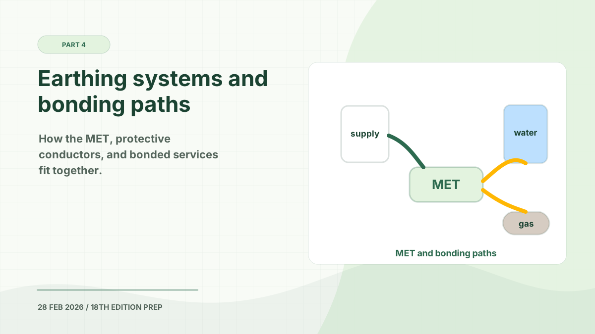
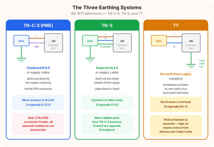
A TT earthing system uses an earth electrode installed and maintained for the consumer’s installation. Unlike TN-S and TN-C-S, the installation does not rely on a protective-earth terminal supplied by the distribution network.
TT is common where a DNO earth terminal cannot be provided safely, at some rural and overhead-line supplies, and where a designer intentionally creates a separated earthing arrangement for part of an installation.
In This Guide
How a TT System Works
The two letters each represent a direct connection to Earth:
- The first T means the supply source has a point connected directly to Earth.
- The second T means the installation’s exposed-conductive-parts connect to a local earth electrode that is electrically independent of the distributor’s protective earthing facility.
The installation’s circuit protective conductors connect to the main earthing terminal, which connects through the main earthing conductor to the electrode.
Permitted electrode forms can include rods, tapes, plates, suitable foundation metalwork, and other arrangements meeting the current BS 7671 requirements. An earth rod is common, but it is not automatically the correct choice for every site.
Why TT Normally Uses RCD Protection
An earth fault on a TT system returns through the consumer electrode, the general mass of Earth, and the supply earthing arrangement.
This path normally has much higher impedance than the metallic return path of a TN system. The resulting fault current may be too small to operate a fuse or circuit breaker within the required disconnection time.
An RCD is therefore normally used for fault protection. It detects the imbalance between line and neutral current and disconnects without relying on a large earth-fault current.
The design must also consider protection before the first RCD, select suitable devices, and avoid an earth fault to exposed metalwork that could remain connected upstream of the protective device.
The RA × IΔn Formula
The central TT relationship is:
RA × IΔn ≤ 50 V
Where:
| Symbol | Meaning |
|---|---|
| RA | The combined resistance of the earth electrode and the protective conductor connecting it to exposed-conductive-parts |
| IΔn | The rated residual operating current of the RCD |
| 50 V | The conventional touch-voltage limit used in the relationship |
For a 30 mA RCD, the arithmetic gives a theoretical maximum of approximately 1667 Ω. That number must not be treated as a desirable electrode result.
TT Earth Electrode Resistance
IET guidance says the electrode resistance should be as low as practicable and warns that a value exceeding 200 Ω may not be stable. Soil moisture, freezing, drying, electrode depth, corrosion, and seasonal conditions can all affect the result.
This means two tests are needed in the design reasoning:
- Does the protective arrangement satisfy the required RCD relationship and disconnection conditions?
- Is the electrode result low and stable enough to remain dependable over time?
A reading that merely falls below the mathematical 1667 Ω limit can still be a poor engineering result.
Ze, Zs and RA on TT
These terms are easily confused:
- Ze describes the external part of the earth fault loop on the supply side. On TT, it does not include the consumer’s earth electrode resistance.
- RA includes the installation electrode and its protective connection.
- Zs is the total earth fault loop impedance for the circuit at the test point.
The often-quoted DNO value of about 21 Ω for TT is not the resistance of the consumer’s electrode and should not be used as if it were an electrode test result.
Testing a TT Earthing System
Verification can include:
- Confirming the earthing arrangement with the DNO
- Inspecting the electrode type, position, connections, labels, and protection against damage
- Measuring earth electrode resistance using an appropriate method
- Confirming main earthing and bonding continuity
- Verifying RCD selection and operation
- Checking circuit disconnection requirements and complete loop results
- Considering soil conditions and the likelihood of seasonal variation
Earth-electrode testing and work around live equipment must be carried out by a competent person. Before driving an electrode, underground cables, pipes, and other services must be located.
TT Compared with TN-S and TN-C-S
| Feature | TT | TN-S | TN-C-S |
|---|---|---|---|
| Installation earth source | Local earth electrode | Separate DNO protective path | DNO PEN conductor, then separated |
| Fault path | Through electrode and soil | Metallic supply path | Metallic PEN/supply path |
| Normal fault-protection approach | RCD | Overcurrent device and/or RCD as required | Overcurrent device and/or RCD as required |
| Main distinctive concern | Electrode resistance and stability | Supply-earth integrity | Open PEN and diverted neutral current |
Continue with the TN-S earthing system guide, the TN-C-S earthing system guide, or the broader earthing and bonding guide.
Authoritative References
- IET Wiring Matters: TT earthing considerations
- National Grid: information for electrical installers
- IET: consumer units and protective devices FAQs
This guide supports revision and general understanding. TT design, electrode installation, testing, and certification must be completed by a competent person using the current BS 7671 requirements.
Prepare for your exam with our mobile app
690+ practice questions with detailed explanations