TN-C-S Earthing System Explained: PME, Ze and PEN Faults
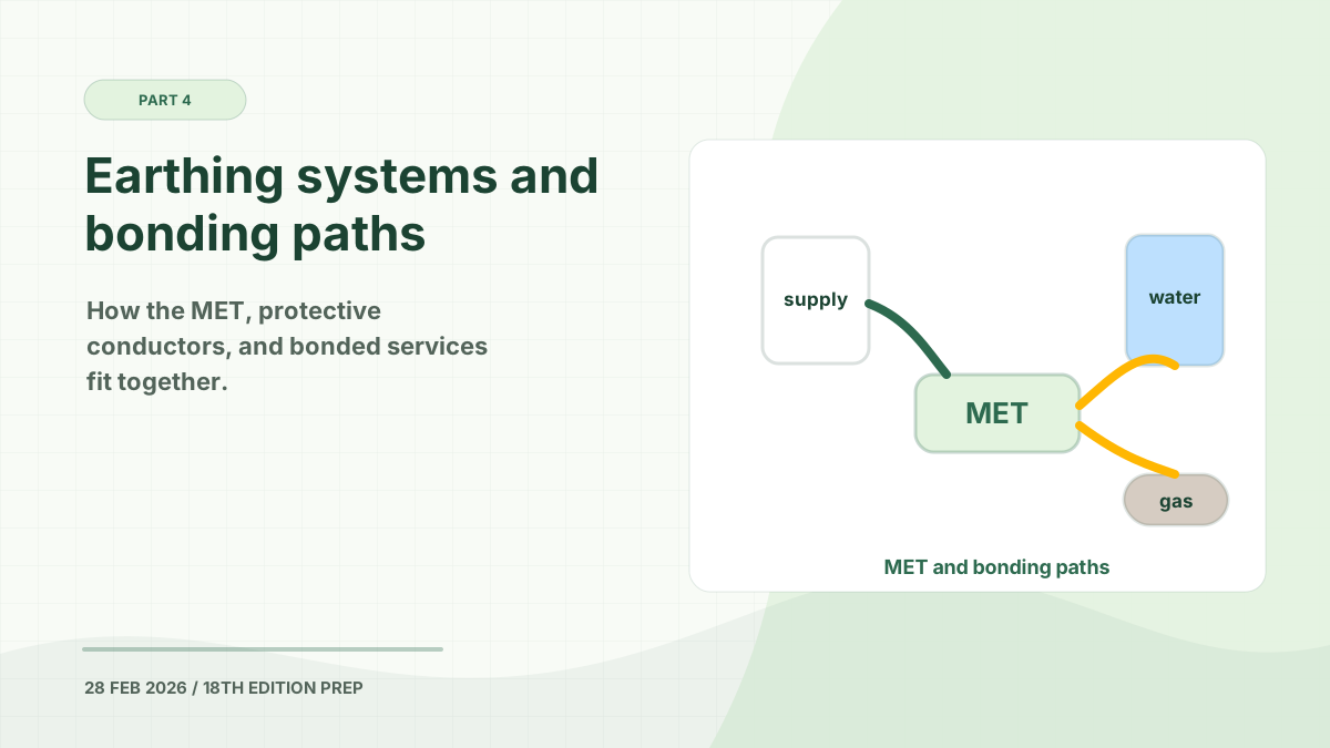
A TN-C-S earthing system is the most common earthing arrangement provided for new UK electricity connections. It is also widely called PME, or Protective Multiple Earthing.
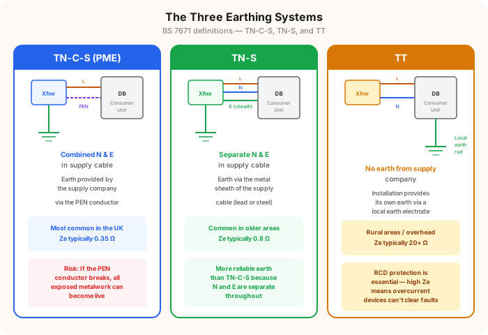
The key feature is the supply-side PEN conductor. PEN stands for protective earth and neutral: one conductor performs both functions through part of the distribution network. At the service position, the protective and neutral functions are separated so that the consumer’s installation has distinct neutral and protective conductors.
In This Guide
How TN-C-S Works
The letters describe the arrangement:
| Letter | Meaning |
|---|---|
| T | One point of the supply source is connected directly to Earth |
| N | The installation’s exposed-conductive-parts connect to the earthed supply point |
| C | Neutral and protective functions are combined in one conductor |
| S | Neutral and protective functions are separated |
The C-S part is the important clue. The distribution network uses a combined PEN conductor for part of its length. The conductor is then split into separate neutral and protective-earth connections for the consumer.
Inside the installation, circuit protective conductors and bonding conductors connect to the main earthing terminal. Neutral and protective conductors must remain separate after the designated separation point.
TN-C-S and PME
TN-C-S and PME are often treated as interchangeable terms, but they describe related ideas:
- TN-C-S describes the combined-then-separate conductor arrangement.
- PME describes the practice of connecting the PEN conductor to Earth at multiple points in the distribution network.
National Grid identifies PME (TN-C-S) as its most common arrangement for new installations. However, network configurations vary, and a supply that visually appears separate at the service position may still derive from a combined-neutral-and-earth network.
Typical TN-C-S Ze
For exam and design work, 0.35 Ω is the familiar typical maximum external earth fault loop impedance, or Ze, associated with TN-C-S.
Treat this as a benchmark rather than a guaranteed measurement. Current National Grid guidance reports 0.34 Ω as a typical maximum covering most premises on its network and explicitly notes that higher values can occur, particularly on long overhead networks or supplies from small pole-mounted transformers.
Practical rule: Obtain supply characteristics from the DNO or verify Ze using an accepted method. Do not assume that every TN-C-S supply will measure exactly 0.35 Ω.
How to Identify TN-C-S
Common clues include:
- A PME or TN-C-S label near the service head
- A main earthing conductor connected to an earthing terminal provided at the service position
- Neutral and protective-earth functions separated at the supply intake
Visual inspection alone is not always conclusive. Do not remove seals or open DNO equipment. If the arrangement is uncertain, ask the DNO to confirm the supply characteristics and have a competent electrician verify the installation.
The Open-PEN Risk
An open PEN fault occurs when the combined protective earth and neutral conductor is broken or has a high-resistance connection.
Because the PEN conductor carries neutral current as well as providing the supply earth reference, an open circuit can raise the voltage of connected protective conductors and bonded metalwork relative to true Earth. Current may also divert through gas pipes, water pipes, structural metalwork, data cabling, or neighbouring installations.
This is why TN-C-S requires particular care for:
- Electric vehicle charging equipment
- Caravans and caravan parks
- Marinas
- Outdoor conductive equipment
- Installations sharing metallic services with other premises
The applicable BS 7671 section may require additional measures or restrict reliance on PME for a particular location.
Bonding Requirements
Main protective bonding connects qualifying extraneous-conductive-parts to the main earthing terminal. On a PME installation, bonding conductor sizing and the possibility of diverted neutral current require careful attention.
Do not assume that every metal pipe needs bonding solely because it is metal. The electrician must establish whether it is an extraneous-conductive-part and apply the current BS 7671 requirements.
TN-C-S Compared with TN-S and TT
| Feature | TN-C-S | TN-S | TT |
|---|---|---|---|
| Supply earth | Derived from a PEN conductor | Separate supply protective conductor | Consumer earth electrode |
| Common UK term | PME | Cable-sheath or SNE earth | Direct earthing |
| Typical Ze benchmark | 0.35 Ω | 0.8 Ω | Supply Ze and electrode resistance considered separately |
| Main distinctive risk | Open PEN and diverted neutral current | Deterioration or alteration of the supply earth path | Electrode stability and high earth fault loop impedance |
Continue with our guides to the TN-S earthing system and TT earthing system, or read the broader earthing and bonding guide.
Authoritative References
- National Grid: information for electrical installers
- IET Wiring Matters: broken PEN conductors
- IET Wiring Matters: external earth fault loop impedance
This guide is for revision and general understanding. Earthing identification, testing, design, and alteration must be carried out by a competent person using the current BS 7671 requirements and verified supply information.
Prepare for your exam with our mobile app
690+ practice questions with detailed explanations