TN-S Earthing System Explained: Diagram, Ze and Identification
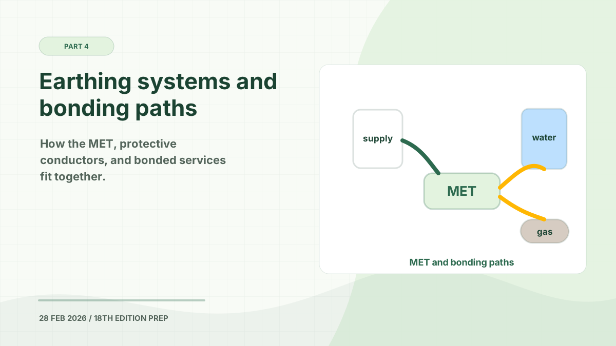
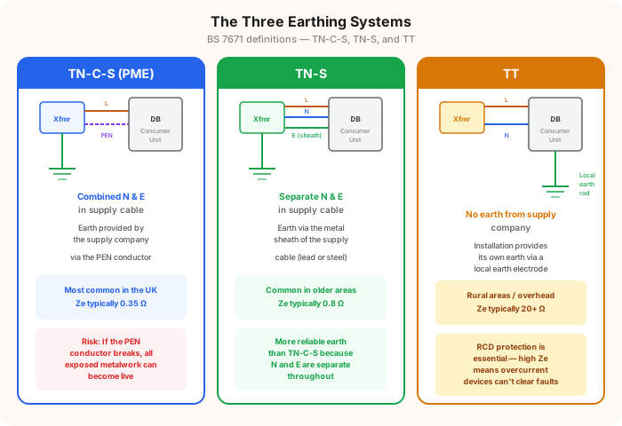
A TN-S earthing system keeps the supply neutral and protective-earth functions separate throughout the network connection to the installation. The traditional UK example uses the metallic sheath or armour of the incoming supply cable as the protective conductor.
TN-S was once common on underground cable networks. It is now less common as networks have been repaired, reinforced, or converted using combined neutral-and-earth sections.
In This Guide
How TN-S Works
The letters have the following meaning:
| Letter | Meaning |
|---|---|
| T | One point of the supply source is connected directly to Earth |
| N | The installation’s exposed-conductive-parts connect to that earthed supply point |
| S | Neutral and protective functions use separate conductors |
In a traditional cable-sheath TN-S arrangement:
- The transformer neutral is connected to Earth.
- The supply neutral reaches the installation on its own conductor.
- The cable sheath or a dedicated protective conductor provides the earth-fault return path.
- The consumer’s main earthing conductor connects the DNO earth terminal to the installation’s main earthing terminal.
Because neutral and protective functions remain separate, TN-S does not use a PEN conductor in the supply path to the installation.
Typical TN-S Ze
The familiar exam and design benchmark for the typical maximum external earth fault loop impedance, or Ze, on TN-S is 0.8 Ω.
This is not a universal guaranteed value. Current National Grid information gives 0.73 Ω as a typical maximum for its cable-sheath or separate-continuous-earth arrangements and warns that network conditions can produce other values.
Use the benchmark to understand the system—not as a substitute for verification. Obtain the supply characteristics or establish Ze using an accepted method before relying on it in a design or certificate.
How to Identify TN-S
A traditional TN-S service may show:
- The main earthing conductor connected to a clamp or terminal on the metallic sheath of the incoming cable
- No PME label at the service position
- A DNO-provided earth terminal described as SNE or cable-sheath earth
However, appearance can mislead. A service may look like TN-S at the cut-out while part of the upstream network has been converted to combined neutral and earth. National Grid notes that where combined sections exist, the arrangement may need to be classified as TN-C-S.
Never disturb the cut-out, seals, cable sheath, or DNO connections. Ask the DNO to confirm the arrangement if it is not documented.
TN-S Testing and Verification
An electrician verifying TN-S considers:
- The declared or measured external earth fault loop impedance
- Continuity of the supply earth connection
- Main earthing and protective-bonding conductor condition
- Evidence of alterations, corrosion, or an unreliable cable-sheath connection
- Required circuit disconnection times and protective-device characteristics
The assumed label is less important than the verified performance and condition of the protective path.
Does TN-S Need RCD Protection?
Yes, where the current BS 7671 requirements call for it.
TN-S usually provides a low-impedance metallic earth-fault return path, so an overcurrent protective device may provide fault protection where the design conditions are satisfied. That does not remove requirements for additional protection by RCD, nor other RCD requirements for concealed cables, socket outlets, outdoor equipment, bathrooms, EV charging, or other special situations.
TN-S Compared with TN-C-S and TT
| Feature | TN-S | TN-C-S | TT |
|---|---|---|---|
| Neutral and earth in supply | Separate | Combined for part, then separate | No DNO earth terminal relied upon |
| Traditional protective path | Cable sheath or separate conductor | PEN conductor in network | Consumer earth electrode |
| Typical Ze benchmark | 0.8 Ω | 0.35 Ω | Supply Ze and electrode resistance assessed separately |
| Main inspection concern | Integrity and classification of the supply earth | Open PEN and diverted neutral current | Electrode resistance, stability, and RCD operation |
Continue with the TN-C-S earthing system guide, the TT earthing system guide, or the complete earthing and bonding overview.
Authoritative References
- National Grid: information for electrical installers
- IET Wiring Matters: external earth fault loop impedance
- IET: earthing and bonding FAQs
This page is a revision guide, not a design certificate. Supply identification, live testing, and any alteration to an earthing arrangement must be handled by a competent person.
Prepare for your exam with our mobile app
690+ practice questions with detailed explanations